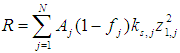
 Eq. 1
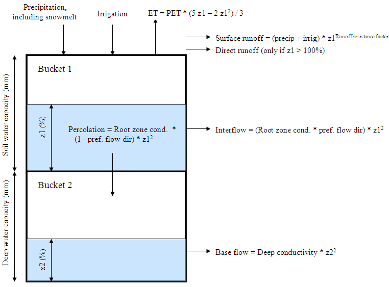
Eq. 1This one dimensional, 2-compartment (or "bucket") soil moisture accounting scheme is based on empirical functions that describe evapotranspiration, surface runoff, sub-surface runoff (i.e., interflow), and deep percolation for a watershed unit (see Figure 1). This method allows for the characterization of land use and/or soil type impacts to these processes. The deep percolation within the watershed unit can be transmitted to a surface water body as baseflow or directly to groundwater storage if the appropriate link is made between the watershed unit node and a groundwater node.
A watershed unit can be divided into N fractional areas representing different land uses/soil types, and a water balance is computed for each fractional area, j of N. Climate is assumed uniform over each sub-catchment, and the water balance is given as,
Eq. 1
where z1,j = [1,0] is the
relative storage given as a fraction of the total effective storage of
the root zone,  (mm) for land cover fraction, j. The effective
precipitation, Pe , includes
snowmelt from accumulated snowpack in the sub-catchment, where mc is the melt coefficient given as,
(mm) for land cover fraction, j. The effective
precipitation, Pe , includes
snowmelt from accumulated snowpack in the sub-catchment, where mc is the melt coefficient given as,
 Eq. 2
Eq. 2
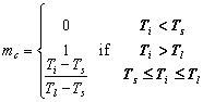
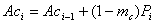
where Ti is the observed temperature for month i, and Tl and Ts are the melting and freezing temperature thresholds. Snow accumulation, Aci, is a function of mc and the observed monthly total precipitation, Pi, by the following relation,
 Eq. 3
Eq. 3
with the melt rate, mr, defined as,
 Eq. 4
Eq. 4
The effective precipitation, Pe, is then computed as
 Eq. 5
Eq. 5
If the timestep length is less than one month (General, Years and Time Steps) then the snow accumulation and melt model is modified to restrict the snow melt rate by the total heat available to transform ice to water. The total heat available is calculated as the sum of the net solar radiation and the heat introduced to the snow pack by rainfall. Albedo for the net solar radiation calculation is computed as a broken linear function of snow accumulation and timestep length, ranging in value from Albedo Lower Bound to Albedo Upper Bound, according to the table below. In this way, a monthly model needs a much deeper snowpack to hit the upper bound, which accounts for snow getting older or melting during the month. For example, in a monthly model, NumDays = 30 (+/-), so the values in the first column below are 0 mm, 30 mm, 150 mm and 300 mm. If the depth of snow at the beginning of January was 60 mm, the albedo would 0.19. Any snow depth over the last value equal the Albedo Upper Bound. The user is able to change what the Albedo Lower Bound and Albedo Upper Bound, but if left blank they will default to 0.15 and 0.25.
|
Snow Depth [mm] |
Albedo |
Albedo, using default bounds of 0.15 and 0.25 |
|
0 |
Albedo Lower Bound |
0.15 |
|
1 * NumDays |
Albedo Lower Bound + 1 * (Albedo Upper Bound - Albedo Lower Bound) / 3 |
0.18 |
|
5 * NumDays |
Albedo Lower Bound + 2 * (Albedo Upper Bound - Albedo Lower Bound) / 3 |
0.22 |
|
10 * NumDays |
Albedo Upper Bound |
0.25 |
In Eq 1., the calculation for the potential evapotranspiration, PET, is done using the reference crop calculation described in the Handbook of Hydrology (1993) in section 4.15, equation 4.2.31. This is the Penman-Monteith equation modified for a standardized crop of grass, 0.12 m in height and with a surface resistance of 69 s/m. In this implementation two modifications to the equation were made: the albedo varies over a range of 0.15 to 0.25 as a function of snow cover (although the user can override this calculation and specify albedo directly), and the soil heat flux term, G, has been ignored.
Continuing with Eq 1, the kc,j is the crop/plant coefficient for each fractional land cover. The third term represents surface runoff, where RRFj is the Runoff Resistance Factor of the land cover. Higher values of RRFj lead to less surface runoff. The fourth and fifth terms are the interflow and deep percolation terms, respectively, where the parameter ks,j is an estimate of the root zone saturated conductivity (mm/time) and fj is a partitioning coefficient related to soil, land cover type, and topography that fractionally partitions water both horizontally and vertically. Thus total surface and interflow runoff, RT, from each sub-catchment at time t is,
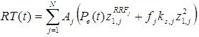 Eq. 6
Eq. 6
For applications where no return flow link is created from a catchment to a groundwater node, baseflow emanating from the second bucket will be computed as:
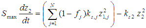 Eq. 7
Eq. 7
where the inflow to this storage, Smax is the deep percolation from the upper storage given in Eq. 1, and Ks2 is the saturated conductivity of the lower storage (mm/time), which is given as a single value for the catchment and therefore does not include a subscript, j. Equations 1 and 7 are solved using a predictor-corrector algorithm.
When an alluvial aquifer is introduced into the model and a runoff/infiltration link is established between the watershed unit and the groundwater node, the second storage term in Eq. 7 is ignored, and recharge R (volume/time) to the aquifer is
 Eq.
8
Eq.
8
where A is the watershed unit's contributing area. The stylized aquifer characterizes the height of the water table relative to the stream, where individual river segments can either gain or lose water to the aquifer (see Groundwater-Surface water Interactions).
Figure 1. Conceptual diagram and equations incorporated in the Soil Moisture model
Yield is a function of maximum potential yield, the amount of water available for evapotranspiration (as a fraction of full potential ET) and a yield response factor:
Yield = MaximumPotentialYield * (1 - YieldResponseFactor
* (1 - (ETActual / ETPotential) ) )
MarketValue = Yield * Area * MarketPrice
where
ETPotential = PET * Kc
ETActual = ETPotential * (5 z1
- 2 z12)
/ 3
Irrigation runoff can be included in total runoff emanating from a catchment. WEAP calculates this irrigation runoff by first assuming no irrigation exists and calculating flows accordingly. WEAP then performs the calculations incorporating irrigation, assuming all requested irrigation is supplied. Knowing how much more runoff would flow due solely to irrigation, WEAP calculates an "average" irrigation runoff fraction (that goes to a river and/or groundwater). This fraction is then applied to the quantity of irrigation that was actually supplied, and essentially becomes the runoff fraction. Note: this irrigation runoff fraction is specified as data by the user when simulating a catchment with the Simplified Coefficient method.
Some fraction of a catchment's runoff can be used for irrigation internally within the catchment (diverted before it reaches surface water inflow of runoff link), via the "Irrigation Use of Runoff" variable. This will allocate some or all of the runoff for use by the catchment for its irrigation, even if there are higher priority demands downstream, and before all other irrigation supplies the catchment would otherwise use. However, runoff from irrigation is NOT available to be used again for irrigation -- this would be circular. Only the runoff from precipitation and from the soil moisture at the beginning of the timestep is available for irrigation within the catchment. Only runoff links to surface water are considered, not infiltration links to groundwater.
TotalRunoff = RunoffNoIrrigation - RunoffUsedForIrrigation + AverageIrrigationRunoffFraction * TotalIrrigation
RunoffUsedForIrrigation = Min(RunoffAvailableForIrrigation, SupplyRequirement) ' do not exceed the total irrigation demand
RunoffAvailableForIrrigation = RunoffNoIrrigation * IrrigationUseOfRunoffFraction
TotalIrrigation = RunoffUsedForIrrigation + IrrigationFromOtherSupplies
where
RunoffNoIrrigation = calculated runoff assuming no irrigation
AverageIrrigationRunoffFraction = calculated average fraction of applied irrigation that will run off
IrrigationUseOfRunoffFraction = data
IrrigationFromOtherSupplies = calculated by WEAP allocation algorithm, based on availability of supplies and other higher priority demands in the system
Standing water on the land surface, also known as "flooding" or "ponding," can occur due to rice cultivation, managed or unmanaged wetlands, or river flooding onto a floodplain. In the case of rice cultivation, irrigation is applied if the level falls below the minimum depth to bring it to the target depth, and can be released and replenished in order to maintain the desired water temperature for the rice. The water can be held in place either by artificial structures (e.g., a dike, for rice cultivation) or by the natural topography of the land. Once the water depth reaches the level of the confinement, it will overflow and runoff to the river along the runoff link.
Ponding can exist only when the root zone is saturated (z1 = 1). The Soil Moisture Method calculates fluxes out of the root zone due to evapotranspiration, interflow and deep percolation, which will occur at their maximum rates when z1 = 1. As water leaves the top bucket, ponded water will enter the soil to take its place, causing the depth of water above ground to decrease. In addition, any water released because of the release requirement will also decrease the depth above ground.
If the root zone is saturated, water can pond on the surface if there is a confinement in place to hold it (Maximum Depth) and/or hydraulic restrictions on the outflow (Flood Return Fraction). A mass balance equation of inflows and outflows tracks the amount of water stored on the surface from one timestep to the next:
SurfaceStoraget = SurfaceStoraget-1 - PETt - InfiltrationToTopBuckett - ReleaseRequirementt - Overflowt + Precipitationt + Irrigationt + RiverFloodInflowt-1
where
InfiltrationToTopBucket = amount of water needed to saturate top bucket
ReleaseRequirement = "Flow through" requirement, if any, to bring in fresh/cooler water for rice
Overflow = Max[ 0, (SurfaceStorage - MaximumDepth ) * FloodReturnFraction ]
Irrigation = amount of water needed to get to TargetDepth { if SurfaceStorage < MinimumDepth }
= 0 { if SurfaceStorage >= MinimumDepth }
RiverFloodInflow = river flood inflow to subcatchment from previous timestep
MinimumDepth, MaximumDepth, TargetDepth and ReleaseRequirement are data variables -- see Flooding for more information.
You may enter an optional Volume Surface Area Elevation (VSE) curve to specify the flooded area and volume at different depths. This is optional -- if you do not enter a VSE curve, the subcatchment's area will be assumed to be level, which will mean that any amount of flooding will flood the entire area of the subcatchment to an equal depth.
The optional glacier module can track the accumulation and melt of ice on the land surface. (To turn on the glacier module for a catchment, go to Category: Advanced, Tab: Model Glaciers? See Soil Moisture Method Glaciers for details on the glacier data variables.) All branches in a catchment will have the same ice and snow depth if climate data are entered at the catchment level.
The depth of ice increases or decrease because of old snow transforming into ice, or existing ice melting. Snow which has not melted after twelve months transforms into ice. Ice will melt only if there is no snow covering it, and the temperature is above a threshold.
|
IceMeltt |
= |
(RNett * GlacierRadiationCoeff * NumDayst / LambdaFusion / pw / 1.1) |
{ If SnowDeptht = 0 and Tt >= TIceMelt } |
|
|
= |
0 |
{ If SnowDeptht > 0 or Tt < TIceMelt } |
SnowIntoIcet
= Snowt-12 {only snow that
has not melted since it fell 12 months ago}
IceDeptht = IceDeptht-1
+ SnowIntoIcet - IceMeltt
where
IceDeptht = average depth
of ice[mm] for the branch or catchment, in timestep t. IceDepth0 = Initial Ice
Depth (input data)
IceMeltt
= depth of ice that melts[mm]
SnowDeptht
= average depth of snow[mm] for the branch or catchment
Tt
= air temperature[C]
TIceMelt
= temperature[C] at which ice begins to melt
RNett
= Net Radiation[MJ/m^2/day]
GlacierRadiationCoeff = fraction of net radiation that contributes to melting
ice
NumDayst
= number of days in timestep t
LambdaFusion = latent heat of fusion -- energy required to melt
a kg of ice = 0.334[MJ/kg]
pw = density of water
= 1000 kg/m^3, divided by 1.1 to account for ice's lower density than
water
SnowIntoIcet = 12-month-old snow
(that has not melted) that transforms into ice[mm]
For the purposes of the mass balance and melt and accumulation equations the glacier depth is considered uniform, so that
GlacierVolume = IceDepth * SubCatchmentArea
where
GlacierVolume = glacier
volume[km^3]
SubCatchmentArea = total area of the subcatchment branch[km^2]
Even though the depth is considered uniform, WEAP can use the relationship between Volume and Area to estimate the actual areal extent of the glacier (which could be less than the SubCatchmentArea) in order to report the area of the glacier. This area will NOT be used for calculating melt or accumulation.
GlacierVolume = c * GlacierAreab
or
GlacierArea = (GlacierVolume / c)(1/b)
where
GlacierVolume = glacier
volume[km^3]
SubCatchmentArea = total area of the subcatchment branch[km^2]
GlacierArea = estimated glacier area[km^2]
c and b are scaling factors
related to the width, slope, side drag and mass balance of a glacier.
Analysis of 144 glaciers around the world suggests factor values of b
= 1.36 and c = 0.048 (Bahr et al. 1997; Klein and Isacks 1998).
Ice melt is split between runoff to surface water and infiltration to groundwater, according to the Infiltration to Groundwater data variable.
RunoffToGW = IceMelt * InfiltrationToGW
RunoffToSW = IceMelt * (1 - InfiltrationToGW)
Note: There is no evapotranspiration or infiltration of precipitation into the upper soil layer when IceDepth > 0, although subsurface flows (interflow, percolation) still take place.