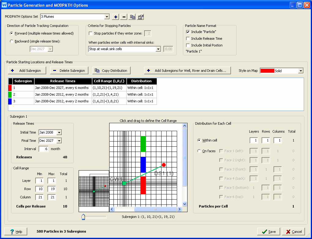
It is on this screen that you will set the main options for your MODPATH analysis, including the starting position for particles that will be tracked over time. As a convenience, you may store many different sets of options, so that you can quickly switch from one to another. For example, you could have different Option Sets for different capture zone analyses (backward tracking from each of several wells or drains), and other Options Sets to look at the plume resulting from particle releases in different locations or release times (forward tracking from particle release points). When you exit this screen, whichever Options Set is listed in the MODPATH Options Set drop down list at the top will be active. (You will also be able to change the active Options Set from the Results View.) You may use the buttons to the right to Add, Delete, Copy or Rename the current Options Set.
MODPATH provides the option of tracking particles forward in the direction of groundwater flow, or backward toward points of recharge. Backward tracking is accomplished by multiplying all velocity components by -1. Once the sign of the velocity components has been changed, computations are carried out in exactly the same way as for forward tracking. For backward tracking, particles terminate at points of recharge, rather than points of discharge. The backward tracking option often provides an efficient means of delineating the source of recharge to localized points of discharge, such as well fields or drains. For a forward tracking analysis, you may release particles at different times, whereas for a backward tracking analysis particles are traced backwards in time from a single release time (typically the last time step of the WEAP model).
A particle terminates when it:
reaches a cell face that is a boundary of the active grid,
enters a cell with a strong sink from which there is no outflow to other cells (or, for backward tracking, a strong source cell with no inflow from other cells),
reaches an external boundary or internal sink/source cell that captures the particle,
enters a cell with a special zone code that is designated as a stopping point, or
is stranded in a dry cell.
If a special zone code is given, MODPATH will terminate a particle if it enters a cell that has been assigned that zone code value. This option can be used to map out the recharge area for a hydrogeologic unit by setting the zone code for the cells that contain that unit equal to the special zone code for terminating particles. If you select this option, you will need to edit the IBOUND array in the MODPATH Main file. The zone code is an integer greater than one.
A weak sink is a model cell (representing a well, for example) that does not discharge at a sufficiently large rate to capture all of the flow entering the cell; thus, some of the flow leaves the cell across one or more of the cell faces. Because of this limitation of model discretization, flow paths to weak sink cells cannot be uniquely defined, as it is impossible to know whether a specific water particle discharges to the sink or passes through the cell. For cells with weak sinks, an arbitrary decision must be made by the user about whether to stop particles. MODPATH provides three options, which apply for backward tracking as well as forward tracking:
particles pass through cells with weak sinks.
particles are stopped when they enter cells with weak sinks.
particles are stopped when they enter cells where discharge to sinks is larger than a specified fraction of the total inflow to the cell. For this last option, enter a fraction between 0 and 1.
These options determine the name shown in the chart legend in the Results View for each particle pathline. As you change the options, an example of how the name will appear is shown below the checkboxes, e.g., "Particle 1."
Starting locations for particles can be generated in one or more rectangular blocks of cells. Each subregion represents one rectangular block of cells--you must have at least one subregion, although it can contain as few as one cell. Use the "Add Subregion" and "Delete Subregion" buttons to add and delete subregions.
In the case of forward tracking analyses, particles also can be assigned a "release time," which allows particles to be released into the flow system over a range of times rather than simply as a single, instantaneous release. Using Initial Time, Final Time and Interval, choose the times in which particles for this subregion will be released. These options are not available for backward tracking.
Specify the extent of the subregion, by specifying the Minimum and Maximum Layer, Row and Column. Each release time specified above will release particles into the same block of cells. (MODFLOW occasionally refers to these three dimensions by the letters I, J, K, with row being the I-axis, column the J-axis, and layer the K-axis, and sometimes by the letters X, Y, Z, with row being the Y-axis, column the X-axis, and layer the Z-axis (elevation). When shown as three numbers together, such as (1, 13, 24), the order is (Layer, Row, Column).) The total number of cells will be the product of the number of layers, rows and columns. For example, if particles will be released in 2 layers, 4 rows and 12 columns, the total number of cells will be 2 * 4 * 12 = 96. As a special case, when Minimum and Maximum Layer = 0, particles are placed in the first active layer for each areal cell location within the subregion. Particles can be draped over the water table surface by placing them on face 6 of all the cells in the subregion.
The cell ranges for every subregion are shown on the map, color coded by subregion. Use the dropdown box labeled "Style on Map" to change whether the cells are displayed with a solid color or with a pattern on the map on this screen. You can also select the cells by clicking and dragging with the mouse on the map--this method is used to choose the rows and columns; to choose the layers, you must use the keyboard.
For a typical backwards analysis, particles are released at sinks, such as well, river or drain cells. Click the "Add Subregions for Well, River and Drain Cells..." button to select which of these cells to add and the distribution for each cell.
You can release one or more particles per cell. Locations of particles for each cell can be generated either as a 3-dimension array of particles inside the cell ("within cell"), or as a 2-dimension array around one or more of the six faces of the cell ("on faces").
If you choose "within cell," specify the number of particles within each cell along the layer, row and column dimensions. The number of particles within the cell is the product of these three numbers.
If you choose "on faces," select which faces on which you would like to place particles. For each selected face (Face 1 = left face, Face 2 = right face, Face 3 = front face, Face 4 = back face, Face 5 = bottom face, and Face 6 = top face), specify the other two dimensions of particles. For example, for Face 1, a 2x3 array (2 layers, 3 rows) would place 6 particles on the left face of each cell in the subregion.
If you want to use the same distribution in all subregions, you can copy the Distribution from the selected subregion to the others by clicking the "Copy Distribution" button. For example, if you want to analyze the capture zones from several non-contiguous well cells, define a subregion for each well cell, specify the distribution for one subregion, then copy this distribution to the other subregions.
If you are backtracking from a cell with a well, river or drain to define a capture area, it is generally best to place particles on the cell faces rather than distribute them internally within the cell. For example, 16 particles on each of the faces 1-4.
The total number of particles released in each subregion is Number of Releases * Number of Cells per Release * Number of Particles per Cell. The total for all subregions is shown at the bottom of the window. Note: the more particles you have defined, the longer it will take for MODPATH to run and for WEAP to display results.